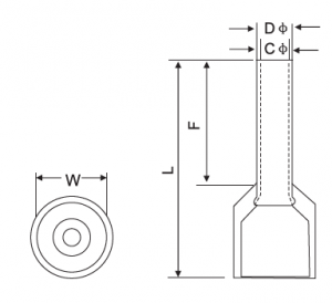
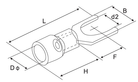
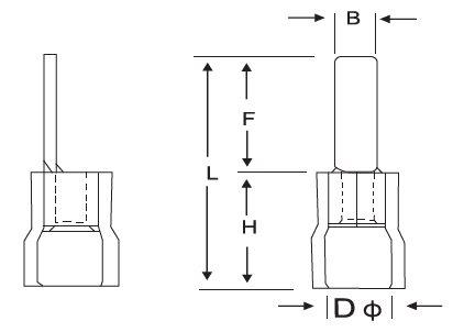
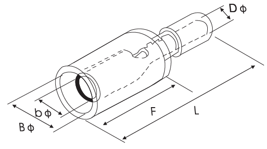
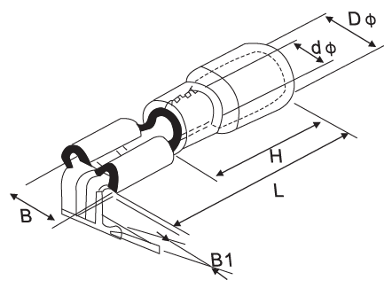
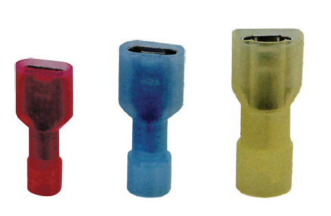
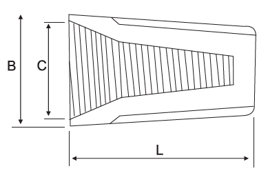
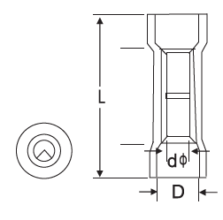
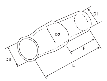
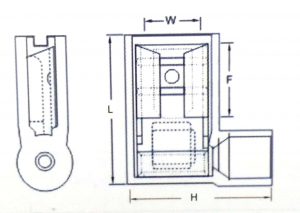
| | d2(mm) | B | L | F | H | Dϕ | |
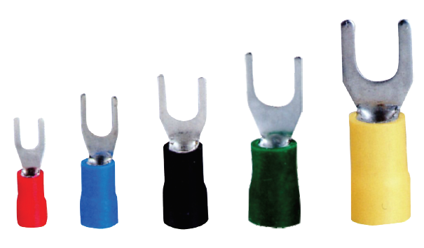
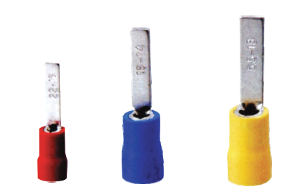
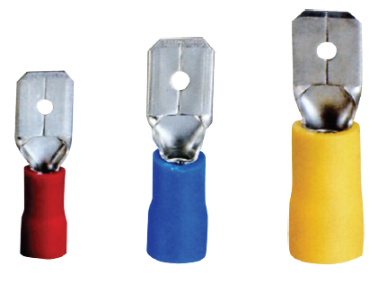
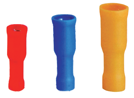
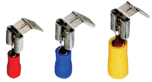
| VR1-3 | #4 | 3.2 | 5.7 | 17.8 | 4.95 | 10 | 4.3 | Material: Copper
Applicable wire range 0.5 ~ 1.5mm 2
AWG 22 ~ 16
maximum current: Imax = 19A |
| VR1-3.5 | #6 | 3.7 | 5.7 | 17.8 | 4.95 |
| VR1-3.5M | #6 | 3.7 | 6.6 | 20.1 | 6.3 |
| VR1-4 | #8 | 3.7 | 7.2 | 21.5 | 7 |
| VR1-4L | #8 | 4.3 | 8 | 21.5 | 7 |
| VR1-5 | #10 | 4.3 | 8 | 21.5 | 7 |
| VR1-5M | #10 | 5.3 | 8 | 21.5 | 7 |
| VR1-5L | #10 | 6.5 | 11.6 | 27.5 | 11.1 |
| VR1-6 | 1 / 4 | 6.5 | 9.5 | 23 | 8 |
| VR1-6L | 1 / 4 | 6.5 | 11.6 | 27.5 | 11.1 |
| VR1-8 | 5 / 6 | 8.5 | 11.6 | 27.5 | 11.1 |
| VR1-10 | 3 / 8 | 10.5 | 13.6 | 31.6 | 13.9 |
| VR1-10L | 3 / 8 | 10.5 | 19.2 | 35 | 16 |
| VR1-12 | 1 / 2 | 13 | 19.2 | 35 | 16 |
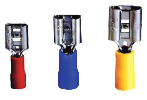
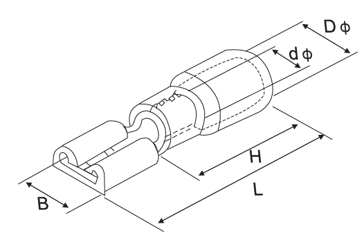
| VR2-3 | #4 | 3.2 | 6.6 | 17.8 | 4.3 | 10 | 4.9 | Material: Copper
Applicable wire range 1.5 ~ 1.5mm 2
AWG 16 ~ 14
maximum current: Imax = 27A |
| VR2-3.5 | #6 | 3.7 | 6.6 | 17.8 | 4.3 |
| VR2-3.5M | #6 | 3.7 | 6.6 | 21 | 7 |
| VR2-3.5L | #6 | 3.7 | 8.5 | 22.5 | 7.75 |
| VR2-4 | #8 | 4.3 | 6.6 | 21 | 7 |
| VR2-4L | #8 | 4.3 | 8.5 | 22.5 | 7.75 |
| VR2-5 | #10 | 5.3 | 8.5 | 22.5 | 7.75 |
| VR2-5L | #10 | 5.3 | 9.5 | 22.5 | 7.25 |
| VR2-6 | 1 / 4 | 6.5 | 9.5 | 22.5 | 7.25 |
| VR2-6L | 1 / 4 | 6.5 | 12 | 27.6 | 11 |
| VR2-8 | 5 / 16 | 8.5 | 12 | 27.6 | 11 |
| VR2-10 | 3 / 8 | 10.5 | 13.6 | 30.2 | 13.9 |
| VR2-10L | 3 / 8 | 10.5 | 19.2 | 35 | 16 |
| VR2-12 | 1 / 2 | 13 | 19.2 | 35 | 16 |
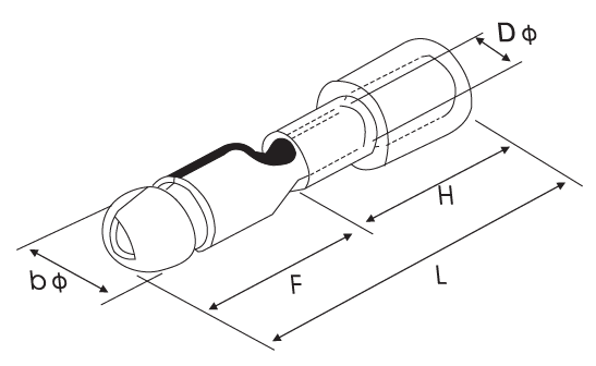
| VR3.5-4 | #8 | 4.3 | 8 | 34.5 | 7.7 | 12.5 | 6.2 | Material: Copper
Applicable wire range 2.5 ~ 4mm2
AWG 14 ~ 12
maximum current: Imax = 37A |
| VR3.5-5 | #10 | 5.3 | 8 | 34.5 | 7.7 |
| VR3.5-5L | #10 | 5.3 | 12 | 27.9 | 7.7 |
| VR3.5-6 | 1 / 4 | 6.5 | 12 | 27.9 | 7.7 |
| VR3.5-8 | 5 / 16 | 8.5 | 15 | 32 | 13.5 |
| VR3.5-10 | 3 / 8 | 10.5 | 15 | 32 | 13.5 |
| VR3.5-12 | 1 / 2 | 13 | 19.2 | 38.1 | 16 |
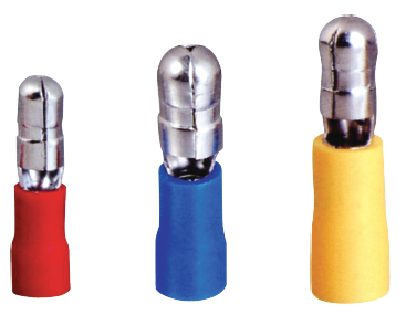
| VR5.5-3.5 | #6 | 3.7 | 7.2 | 21.4 | 5.9 | 12.5 | 6.7 | Material: Copper
Applicable wire range 4 ~ 6mm2
AWG 12 ~ 10
maximum current: Imax = 48A |
| VR5.5-4 | #8 | 4.3 | 7.2 | 21.4 | 5.9 |
| VR5.5-4L | #8 | 4.3 | 9.5 | 25.5 | 8.3 |
| VR5.5-5 | #10 | 5.3 | 9.5 | 25.5 | 8.3 |
| VR5.5-6 | 1 / 4 | 6.5 | 12 | 31.5 | 13 |
| VR8.5-8 | 5 / 16 | 8.5 | 15 | 33.7 | 13.7 |
| VR8.5-10 | 3 / 8 | 10.5 | 15 | 33.7 | 13.7 |
| VR8.5-12 | 1 / 2 | 13 | 19.2 | 38.1 | 16 |